
Every year ASNE welcomes teams from across the nation to compete and Promote Electric Propulsion. I was the Project lead for University at Buffalo’s manned team in 2025-2026 and designed the complete electrical system and related mechanical systems.
Problem Statement
The rules for the competition are as follows; Build a displacement craft that does not get up on plane that cannot use more than 55.5 volts of battery power to finish a 5 mile course the the least time possible.
Background
The design process of the University at Buffalo’s 2026 electrically propelled displacement boat was grounded by a combination of literature review, empirical analysis, and lessons learned from the University at Buffalo’s 2025 competition entry. An analysis of last year’s entry highlighted its key limitations. The boat utilized a 48V, 100Ah battery system powering an air-cooled DC motor, that was able to achieve a maximum speed of ~7 mph. However, based on PEP competition rules, up to 500Ah of energy storage is allowed, indicating that the prior design significantly underused the available energy capacity. To address this, an additional battery was added to increase the total system capacity from 100Ah to 205Ah. Although this is still shy of the competition maximum, it is still an improvement to the previous system while also being economical.
Hull selection was evaluated in conjunction with naval architecture literature. The driving factor was displacement hull theory, which relates maximum speed to effective waterline length. Although a jet-ski hull was available, research showed that jet-skis are optimized for planning rather than displacement. To support this, a CFD analysis was conducted to demonstrate that the catamaran produced a lower hydrodynamic drag when compared to the jet-ski. Based on both theoretical and computational results, the catamaran hull was selected due to its optimal geometry.
The propulsion system was redesigned to address both reliability concerns and efficiency. The original air-cooled DC motor experienced corrosion due to the saltwater at Virginia Beach. To address this, a water-cooled AC motor was selected for improved resistance to the environment and increased power. Additionally, an analysis of the propeller identified an optimal operation at approximately 2,600 rpm with a minimum diameter of 4.75” and three blades. The previous entry allowed no variation of propeller speed; this led to the implementation of a chain and sprocket driven gearbox to better match the motor’s output and optimal propeller requirements. To account for the increased motor output, the original 8hp lower unit was replaced with a 15hp lower unit to ensure reliability.
Finally, boat trim was addressed based on the hydrodynamic principles that relate weight distribution to effective waterline length and drag. The previous design had a majority of components toward the stern decreasing the waterline and in turn reducing performance. By moving the components of the boat to the bow, the center of gravity shifted to the center of the boat, resulting in improved hull efficiency and overall speed. Together, these decisions based on the research conducted allowed for major improvement to the previous electric propulsion system.
Table 1: Design Decision Based on Research Conducted
| Research | Insight | Design Decision |
| PEP competition allows a battery capacity up to 500Ah. | The original system used 100Ah, underusing the allowed capacity. | Increased battery capacity to 205Ah, budget limited. |
| Saltwater corrosion at Virginia Beach. | The air-cooled motor was vulnerable to corrosion. | Switched to a water-cooled motor. |
| Displacement hull theory & CFD analysis. | A longer effective hull length improves speed. Catamaran has a lower drag in displacement conditions. | Selected catamaran hull over jet-ski hull |
| Propeller analysis. | Optimal prop is >4.75”, 3 blades, & spins at 2,600 rpm. | Selected propeller bade around optimal propeller. Added chain-driven gearbox to adjust propeller speed. |
| Drivetrain reliability. | Increased motor power requires a stronger drivetrain. | Changed from an 8hp lower unit to a 15hp lower unit. |
| Hull trim and weight distribution. | Off center mass distribution reduces effective waterline. | Adjusted center of gravity to increase waterline. |
Design and Analysis
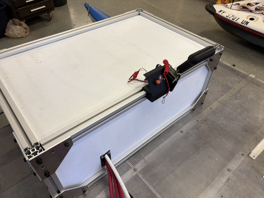
The design of the electrical and mechanical systems largely revolved around the limited budget that was provided to our team. With just $7,200 of working budget it is important to keep the surrounding mechanical systems to our batteries and motor as simple and cheap as possible. This led me to choosing 80/20 aluminum rail as the base for my battery box design. The extruded aluminum rail allows for easy assemble, low manufacturing cost, and allows for future year to expand upon our design with limited change-over. The extruded aluminum frame was a rigid external structure to house the batteries but needed to be sealed which led me to sourcing corrugated plastic from Lowes that is typically used for poster board. In order to get the most strength out of this poster board I cut two pieces per side with the channels in the board perpendicular to each other and bonded them together with five minute epoxy. Once all of the pieces were bonded together they were then inserted into the channels of the extruded aluminum and sealed them with silicone caulk. The battery box and brackets is shown below.
Overview of Build & Fabrication Processes
Power Storage
The power storage is accomplished with an extruded aluminum battery box that will provide a rigid storage space for the batteries and will allow future UB PEP competitors to modify the system to meet their demands. The battery box uses twelve pieces of extruded aluminum that relate to external aluminum bolting brackets that will allow us to keep the internal channels of the extruded aluminum open for a sealing device. The extruded aluminum was marked and cut to size using a reciprocal saw and then sanded on a belt sander to clean cut edges and bring them flush. The aluminum brackets that are used to bolt the extruded aluminum pieces together were laser cut using a DXF and pulling inspiration from McMaster products. The selected sealing device is corrugated plastic sheeting that is bonded in 90-degree rotations to increase the sheet thickness and rigidity, which is then sealed with 3M panel bond to create a watertight seal.
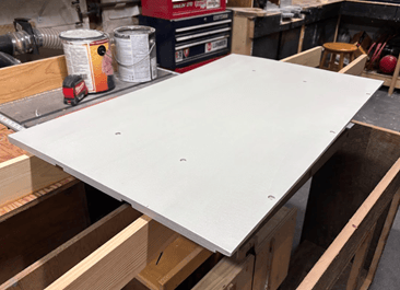
The battery box is located on the boat with an alignment plate. This alignment plate is cut to the inside dimensions of the extruded aluminum frame with a 0.25” gap in each direction to allow for easy installation of the battery box. This plate has channels cut on the underside to clear bolt heads present on the boats platform. The plywood was cut using a table saw to keep each cut square and straight. The channels were also made using a 0.75″ straight flute attached to the table saw. Counterbored holes were then drilled into the top side of the pl3ate using a drill press to keep the top surface flush and ensure the batteries will sit flush on top of this plate. The alignment plate was then coated with exterior deck paint to keep it from dry rotting after exposure to saltwater at the competition.
The purpose of the battery box is to prevent marine exposure and ensure batteries will stay stationary during operation. To test the seal, dyed water was being poured on the sealing edge; areas that allowed water to pass through were resealed with silicon. To test the rigidity of the components in the battery box, the heaviest battery will be placed on top of the longest span of the battery box to test for deflection. If the aluminum deflects more than 1/8”, then bracing will be added.
Controls
The ME 1616 motor will be controlled by a Curtis 1236SE-5671 that supplies 250A of continuous power to the motor. This controller/inverter combination uses a Pb-8 variable resistance throttle to send varied power back to the motor through the 3-Phase high voltage power cords. The boat key that attaches to your wrist is wired directly into the Tyco contactor so in case of a man overboard the power is instantly cut off. Our battery pack consists of four 12V 100Ah batteries that are linked in series with each other and then connected in parallel with a 48V 105Ah battery. This gives the battery pack a total voltage of 48V and 300A BMS with 205Ah. The battery pack wiring was made from scratch this year due to corrosion found on the previous year’s motor wires. 2/0 AWG Tinned wire was selected based on the current output and tinned wiring to prevent corrosion from the saltwater at the competition. Thirty feet of wire were ordered with twenty of the appropriate tinned lug connectors, and lengths were marked and crimped using a hydraulic crimper.
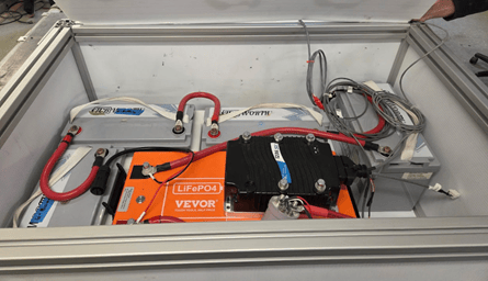
Due to the remote location of the battery box relative to the motor, the team had to send extended 3-Phase wires back to the motor to mount up to a ‘bus bar’ at the motor. Along with sending the high voltage wires to the motor, the Curtis controller was wired with extended communications wires that ran to the motor to make torque and rpm requests. Another low voltage wiring was from the controller to a programming port that also houses the display. It was decided that running the Tyco contactor with a 3-amp fuse, direction switch for reverse, safety boat switch, and a PB-8 throttle was best both safety wise as well as for power efficiency.
Due to the limited budget and ease of design the steering system of the repurposed lower unit remained. This consisted of a tiller style system where an arm protrudes from the outboard system and can be pushed to either direction pivoting the motor, gearbox, lower unit, and propeller to generate trust laterally.
Cooling
The motor is cooled by a custom cooling system consisting of two main loops. The closed hot-water loop serves to pull heat away from the motor with a maximum allowable temperature of 230ºF. Flow in this loop is driven by a Wasserman 12-Volt RV pump. The operating fluid for this loop is standard tap water. The hot water passes through an AB Plate heat exchanger, which transfers heat to the open cold-water loop. The heat exchanger can handle a maximum temperature of 482ºF, which is significantly higher than expected operating temperatures. The cold-water loop pulls water directly from the ocean, passes through the heat exchanger in a counterflow orientation relative to the hot-water loop, then discharges back into the ocean. Flow in this loop is driven by the boat’s forward momentum. The plumbing for the cooling system consists mainly of 0.5” diameter PEX B tubing, and uses both press fit and barbed fittings. For the connection to the motor, flexible vinyl tubing is used to allow the lower unit to pivot freely.
3-D Printed Parts
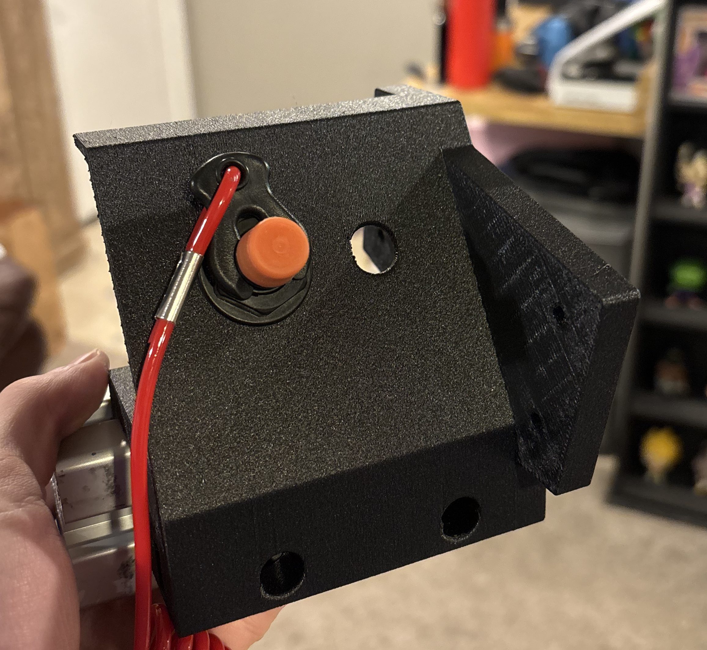
Below is an image of the 3-D printed bracket I made to house the E-stop, Forward-Neutral-Reverse switch, and throttle.
The image below shows the 3-D printed bracket I designed and printed to house the display for RPM and Amp draw as well as the cooling loop on/off switch.
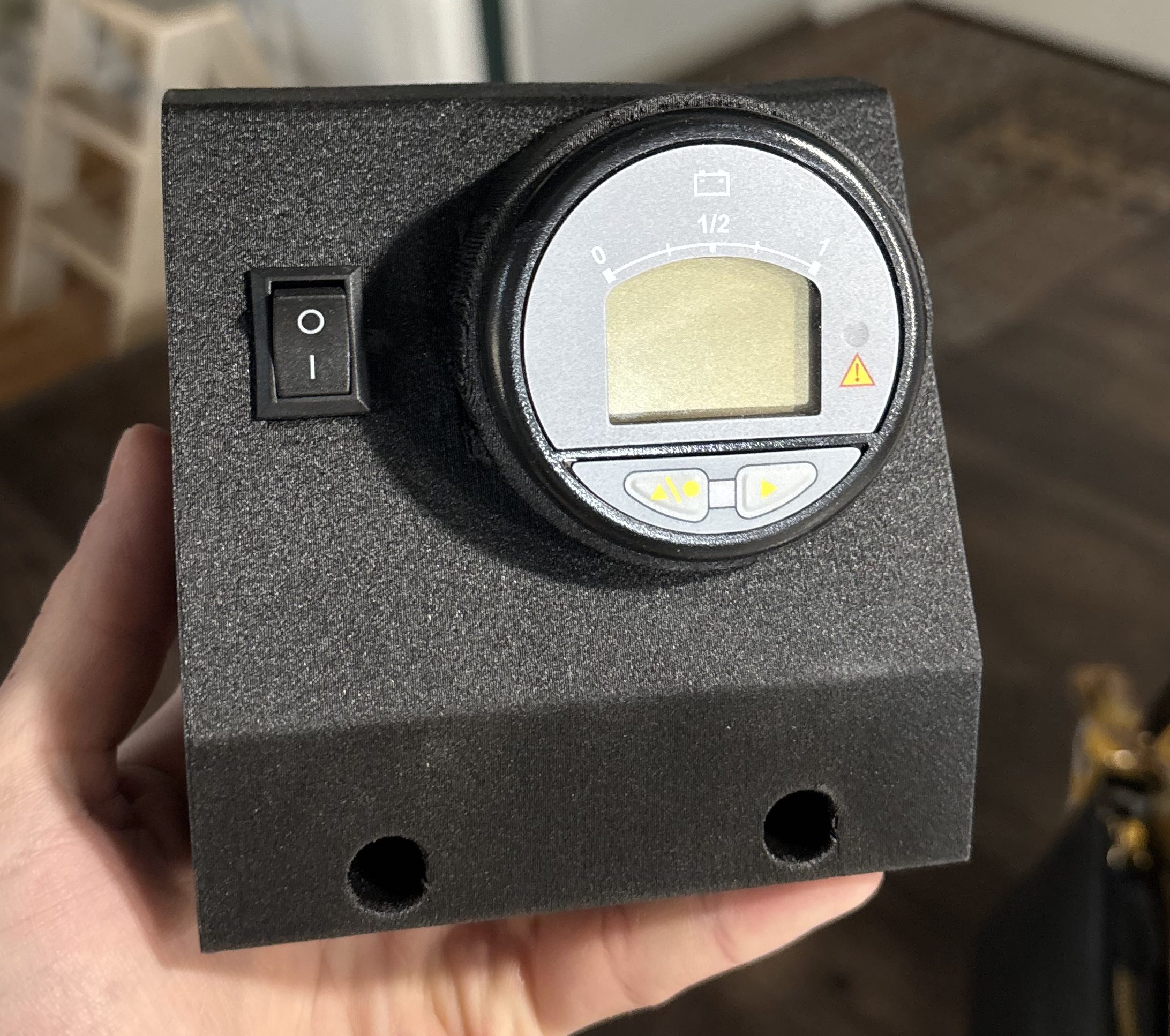
Both of the brackets above simply snapped into the slots in the 80/20 rail and were secured into position with bolts that passed through jam nuts in the 3-D print to keep the ‘dash’ secure during operation.
Conclusion
After all of this hard work our group was able to land 1st place again with a time of 41:40 while only running the boat at half throttle. This is extremely gratifying to see our design come to fruition and mostly go as planned. Our design was heavily focused on making parts reusable for next years team if they choose to reuse components or switch divisions. I look forward to see what University at Buffalo has in store for next years PEP competition.

ANSE PEP26:https://www.navalengineers.org/Education/PEP26
A big thanks to my Team Members below that played major parts in the design and fabrication of this boat.
-Tim Kraycar
-Jason Barnes
-Nick Schuck
-Williams Prevet
-Emma Liang
-Melanie Valladares
-Gabby Schinzel
-Julia O’Malley

 Newton Designs
Leave a comment